Home | Back to RTS-1 Information | ARONTS
Note: this device has been replaced with the RTS-2
Remote Test Set
Model RTS-1
Instruction Manual
RTS-1 Features
* Isolates Telco Lines from:
--- Key Telephone Systems
--- PBX's
--- Automatic Call Distributors
* Separates Line Trouble from Equipment Trouble
* Eliminates Needless Site Visits
* Access from any DTMF Telephone
* Can Remotely:
--- Seize Lines
--- DTMF Dial
--- Pulse Dial
--- Detect Ringing
* Protected by Security Codes
* Nonvolatile Parameter Storage
* Visual Operational Status
* Keeps Track of Test and Program Accesses
* Expands to 56 Lines in 8 Line Increments
Table of Contents
Page
1. Introduction . . . . . . . . . . . . . . . . . . . . . . . . . 4
1.1 How to Use This Manual . . . . . . . . . . . . . . . . . 4
1.2 Applications . . . . . . . . . . . . . . . . . . . . . . 4
1.3 Definitions . . . . . . . . . . . . . . . . . . . . . . 5
1.4 The Remote Test Set Solution . . . . . . . . . . . . . . 7
1.5 Multiple Modules . . . . . . . . . . . . . . . . . . . . 8
1.6 Indicator Lamps . . . . . . . . . . . . . . . . . . . . 8
1.7 Hookup . . . . . . . . . . . . . . . . . . . . . . . . . 9
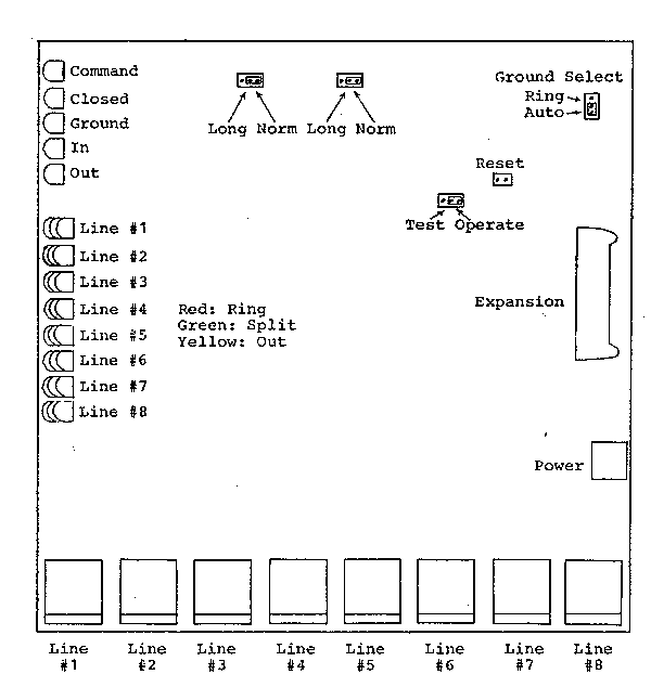
Figure 1-1: Pictorial . . . . . . . . . . . . . . . . . . . 10
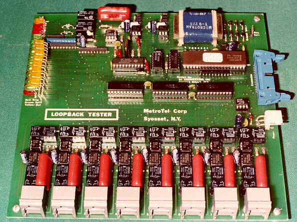
Board Photograph
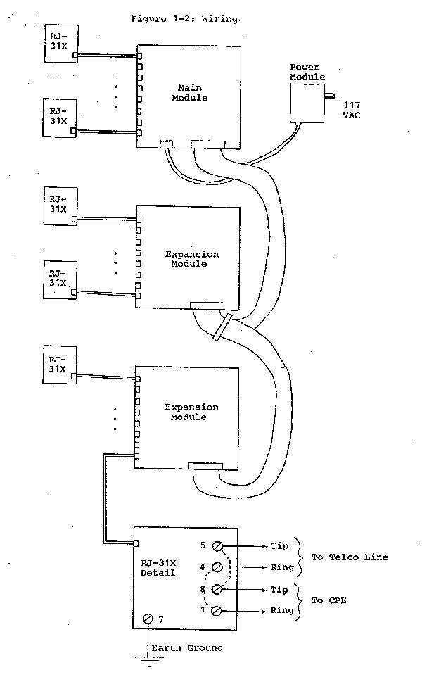
Figure 1-2: Wiring . . . . . . . . . . . . . . . . . . . . . 11
2. Testing Lines . . . . . . . . . . . . . . . . . . . . . . . . 12
2.1 Accessing Test Mode . . . . . . . . . . . . . . . . . . 12
2.2 Seizing a Line . . . . . . . . . . . . . . . . . . . . . 12
2.3 Standard DTMF Dialing . . . . . . . . . . . . . . . . . 13
2.4 Slow DTMF Dialing . . . . . . . . . . . . . . . . . . . 13
2.5 Pulse Dialing . . . . . . . . . . . . . . . . . . . . . 14
2.6 Listening for Ringing . . . . . . . . . . . . . . . . . 15
2.7 Reading Information . . . . . . . . . . . . . . . . . . 15
2.8 Exiting Test Mode . . . . . . . . . . . . . . . . . . . 16
3. Customization . . . . . . . . . . . . . . . . . . . . . . . . 17
3.1 Accessing Program Mode . . . . . . . . . . . . . . . . . 17
3.2 Setting the Number of Rings to Answer . . . . . . . . . 17
3.3 Setting the Number of Modules . . . . . . . . . . . . . 18
3.4 Inhibiting Line Answering . . . . . . . . . . . . . . . 18
3.5 Changing the Test Code . . . . . . . . . . . . . . . . . 18
3.6 Changing the Program Code . . . . . . . . . . . . . . . 18
3.7 Changing Timing Values . . . . . . . . . . . . . . . . . 18
3.8 Parameter Initialization . . . . . . . . . . . . . . . . 19
3.9 Exiting Program Mode . . . . . . . . . . . . . . . . . . 19
4. The Multiple Module Configuration . . . . . . . . . . . . . . 20
5. RTS-1 Confidence Testing . . . . . . . . . . . . . . . . . . . 21
5.1 Testing the Processor EPROM . . . . . . . . . . . . . . 21
5.2 Testing the DTMF Sender . . . . . . . . . . . . . . . . 21
5.3 Testing the DTMF Receiver . . . . . . . . . . . . . . . 21
5.4 DTMF Loop Around Test . . . . . . . . . . . . . . . . . 21
5.5 Cycling Relays . . . . . . . . . . . . . . . . . . . . . 21
5.6 Ring Detection Test . . . . . . . . . . . . . . . . . . 22
5.7 Loop Current Test . . . . . . . . . . . . . . . . . . . 22
6. In Case of Difficulty . . . . . . . . . . . . . . . . . . . . 23
6.1 Unit Does Not Answer Ring . . . . . . . . . . . . . . . 23
6.2 Program Code Forgotten . . . . . . . . . . . . . . . . . 23
6.3 Long Loops . . . . . . . . . . . . . . . . . . . . . . . 23
6.4 Unit Does Not Seize Ground Start Lines . . . . . . . . . 24
7. Command Summary . . . . . . . . . . . . . . . . . . . . . . . 25
Appendix. RTS-1 Equipped for Machine Control
Appendix. RTS-1 Version Options
COMPLIES WITH
PART 68, FCC RULES.
FCC REGISTRATION
NUMBER: AG997G-17336-TQ-E
RINGER EQ: 0.2A and 0.6B
The customer connecting the equipment to the telephone network shall, before
such connection is made, give notice to the telephone company of the particular
line(s) to which such connection is to be made, shall provide to the telephone
company the FCC Registration Number and Ringer Equivalence of the RTS-1,
and shall specify USOC RJ31X. The customer shall give notice to the telephone
company upon final disconnection of the equipment from the particular line(s).
Connection of this equipment to party lines and coin telephone service are prohibited.
Should the equipment cause harm to the telphone network, the telephone company shall, where practicable, notify the customer that temporary discontinuance of service may be required; however, where prior notice is not practicable, the telephone company may temporarily discontinue service forthwith, if such action is reasonable in the circumstances.
The telephone company may make changes in its communications facilities, equipment, operations or procedures, where such action is reasonably required in the operation of its business and is not inconsistent with the rules and regulations in Part 68 of the FCC Rules. If such changes can be reasonably expected to render the customer's equipment incompatible with telephone company communications facilities, or require modification or alteration of such equipment, or otherwise materially affect its use or performance, the customer shall be given adequate notice in writing, to allow the customer an opportunity to maintain uninterrupted service.
The RTS-1 is not user-servicable; in case of malfunction, it must be
returned to the equipment manufacturer.
Warning:
This equipment generates, uses, and can radiate radio frequency energy and if not installed and used in accordance with the instructions manual, may cause interference to radio communications. It has been tested and found to comply with the limits for a Class A computing device pursuant to Subpart J of Part 15 of FCC Rules, which are designed to provide reasonable protection against such interference when operated in a commercial environment. Operation of this equipment in a residential area is likely to cause interference in which case the user at his own expense will be required to take whatever measures may be required to correct the interference.
1. Introduction
This chapter provides an overview of the environments where the Remote
Test Set is utilized. Requirements, definitions, system solutions, multiple
module configurations, installation, and visual displays are discussed.
1.1 How to Use This Manual
Chapters 1 and 2 are sufficient in many instances to cover the material
required to install and operate the RTS-1. Should it be necessary to alter
the factory default parameters, chapter 3 will also be required. If difficulties
arise in using the unit, consult chapter 6. In order to achieve maximum
performance relative to specific needs, it is recommended that the rest
of this manual be examined. Chapter 7 is included as a quick reference.
1.2 Applications
Nearly every business establishment utilizes Customer Premises Equipment (CPE) in order to provide for internal and external telephone communications. Typical products used are: mechanical and electronic Key Telephone Systems; Private Branch Exchange (PBX) switches; and hybrid systems, which are combinations of the two. Additionally, call sequencers and Automatic Call Distributors (ACD's) are placed into service to handle volumes of incoming traffic. In fact, CPE for the most part is universal with the one exception of Centrex service.
Premises equipment is either owned or leased by the end user, who is ultimately responsible for its maintenance. Typically, the end user contracts for such maintenance with an interconnect or service providing company. The CPE handles internal telephone calls entirely on its own. Incoming and outgoing calls are handled through interface with telephone lines provided by the local operating company (Telco). CPE is connected to these Telco lines at the point of interface, or the Demarcation Point. Telephone line problems on the Telco's side of the Demarcation Point are the responsibility of the Telco for repair; troubles on the customer's side of that point are the responsibility of the service company to provide for repair.
In general, the end user is not knowledgable about where a technical malfunction is present; he only knows that his telephone system "doesn't work", and calls the service provider to take care of the problem. The service company dispatches a serviceman to the customer's site, whose first action is usually to take a "butt set" and test the Telco lines at the Demarcation Point. If the lines test good, then a problem actually does exist in the CPE, and troubleshooting begins. If the Telco lines prove inoperative, the next action is to disconnect the CPE from the Telco lines, and test the lines again, since it is possible for the CPE to improperly load or seize the lines and prevent proper operation. Should the Telco lines remain inoperative, then the problem is definitively isolated to the Telco. When this occurs, the service company notifies the Telco of the problem; there is nothing which can be done at the site by the serviceman.
When a site visit results in isolation of trouble to the Telco, the
result is a total waste of technical time, resources, money, and overall
time to repair from the customer's perspective. The service company can
provide better and more efficient response if the trouble can be isolated
to either side of the Demarcation Point prior to dispatch to the customer
site. Key systems cannot provide this in any fashion; some intelligent
PBX's do provide for testing of specific trunk ports via access and service
codes. However, even in the latter case, there is a certain amount of circular
logic employed by using a PBX to test a particular trunk circuit. The result
of such a test can have an absolute negative result: no trouble detected
-- both the Telco line and the trunk card are good. When the test result
is positive in detection of a problem, it is still unknown if the trouble
lies in the Telco line or the trunk card itself -- the same trunk card
is used to test the telephone line as normally accesses the line. It can
be seen that true trouble isolation can effectively be provided only with
a separate means of testing from normal operation.
1.3 Definitions
A brief description of types of telephone lines, signaling, addressing,
and interfaces follows.
2-Wire Line:
A total of two conducting wires are used for bidirectional voice (or
data carrier) transmission. Audio signals in each direction are simultaneously
present and are superimposed on one another. The impedance is typically
600-900 ohms. One twisted pair is used, and the transmission is balanced
(the signal is the voltage difference between the two leads). Two-wire
lines are contrasted with 4-wire lines, in which two twisted pairs are
used, one for transmission in each direction.
Loop Start Signaling:
In the idle state, the terminating equipment (telephone or telephone
system) presents an open circuit to the two telephone leads, designated
as Tip and Ring. The Telco places a DC voltage across the two leads, typically
52.5 volts. To originate a call, the terminating equipment closes the loop
(goes off-hook) by presenting a low DC resistance between the Tip and Ring
leads, permitting loop current to flow. The Telco Central Office (CO) detects
the transition to loop current, and responds by returning dialtone, signifying
that it is ready to receive addressing information (the user can now dial).
When a call is placed to an idle loop start line, the Telco periodically
superimposes an AC ringing voltage (typically 90 volts RMS) on the already
present DC loop voltage across the Tip and Ring leads. The ringing voltage
is nominally present for two seconds and off for four seconds. The AC ringing
voltage directly rings the bell on electromechanical telephones, or is
detected electronically by CPE. The ringing cycle persists until the terminating
equipment answers the call by closing the loop (goes off-hook) in the same
fashion as for originating a call. When the CO detects the presence of
loop current, the ringing cycle is stopped, and a connection is established
between the originating and terminating telephone lines. Once a call is
established, the CPE maintains the loop closure for the duration of the
call. In either case, the call is terminated by opening the loop (going
on-hook). The CO detects the loss of loop current, and after a particular
period of time (typically a fraction of a second for the originating line
and 10-20 seconds for the terminating line), disconnects the call and places
the telephone line in its idle state. Should the opposite end from which
the call was ended (hung up) remain on-hook, a momentary loss of loop current
will occur, signifying the end of the call; subsequently, the loop closure
will be treated as a new originating call, returning dialtone.
Ground Start Signaling:
In addition to the Tip and Ring leads, Earth Ground is used as a third
lead for signaling purposes only. For transmission purposes, only the Tip
and Ring leads are used. In the idle state, the terminating equipment presents
an open circuit to all three telephone leads. The Telco places a DC voltage
on the Ring lead with respect to Ground, typically -52.5 volts. To originate
a call, the terminating equipment connects the Ring lead to Ground. The
CO detects the presence of current through the Ring lead, and responds
by grounding the Tip lead. From this point forward, the operation is identical
to that of a loop start line. The CPE detects the return ground on the
Tip lead and responds by closing the loop between Tip and Ring, and releasing
the ground on the Ring lead. The CO responds by returning dialtone. When
a call is placed to an idle ground start line, the Telco first grounds
the Tip lead. From this point forward, the behavior is identical to that
of a loop start line, i.e. it periodically superimposes an AC ringing voltage
on the now present DC loop voltage across the Tip and Ring leads. The CPE
can either detect the immediate ground on the Tip as an indication of an
incoming call, or detect the ringing voltage as for loop start lines. The
ringing cycle persists until the terminating equipment answers the call
by closing the loop between Tip and Ring in the same fashion as for loop
start lines. When the CO detects the presence of loop current, the ringing
cycle is stopped, and a connection is established between the originating
and terminating telephone lines. Once a call is established, the CPE maintains
the loop closure for the duration of the call. In either case, the call
is terminated by opening the loop (going on-hook). The CO detects the loss
of loop current, and after a particular period of time (typically a fraction
of a second for the originating line and 10-20 seconds for the terminating
line), disconnects the call and places the telephone line into its idle
state. Should the opposite end from which the call was ended (hung up)
remain on-hook, a loss of loop current will occur, signifying the end of
the call; in this way ground start lines provide positive Disconnect Supervision.
DTMF Dialing:
Dual Tone Multi Frequency (DTMF) signifies a method of transmitting
addressing information (dialed telephone number) in-band, i.e. within the
audio channel bandwidth over telephone lines. DTMF signals consist of two
superimposed audio tones, one from a low frequency group and one from a
high frequency group. There are four frequencies used in each group, resulting
in 16 possible pairs of tones. These pairs are assigned to the numeric
digits 1-9 and 0, and the special digits *, #, A, B, C, and D.
Pulse Dialing:
Pulse dialing is a method of transmitting addressing information via
opening (breaking) and closing (making) the DC loop in a telephone line.
Electromechanical telephones with rotary dials directly generate contact
closures when the dial is released, as the spring returns the dial to its
resting position. This operation is also mirrored in electronic telephones
or CPE trunk interfaces electronically. The numeric digits 1 through 9
and 0 are represented by 1 to 10 breaks in loop current, respectively,
sent nominally at a rate of 10 breaks per second. Each break is brief,
as too long of a break would be interpreted as an on-hook status, and cause
a disconnection. Unlike DTMF addressing, pulse dialing is not an in-band
signaling method, and is not propagated through the telephone network and
cannot be used for end-to-end communication.
USOC RJ-31X Interface:
The RJ-31X jack is used to split a telephone line in order to place
equipment between the telephone network and the remainder of the CPE. The
connector is an 8-pin jack, with shorting jumpers which reconnect the telephone
network to the CPE when the plug is removed. With the plug in place, the
CPE is isolated from the Telco line, unless the equipment connected at
the other end of the 8-wire cable restores the through connection.
Customer Premises Equipment (CPE):
This instruction manual refers to the customer's telephone system as
CPE. This equipment can be key systems, PBX's, ACD's, or any other equipment
which is connected to Telco provided lines.
1.4 The Remote Test Set Solution
The RTS-1 is designed to eliminate the needless site visits which otherwise occur when the problem encountered is trouble with the Telco line itself. It provides the equivalent of using a "butt set" at the Demarcation Point, without dispatching a serviceman to the customer's premises. The RTS-1 is accessed through any DTMF telephone in the public switched telephone network. In practice, when a customer complaint is received, the RTS-1 is used to remotely determine if there is a problem with the Telco line; if none is found, a service call is in order to repair the CPE.
The RTS-1 can be used with 2-wire loop or ground start Telco lines, and is connected via RJ-31X jacks at the Demarcation Point. In normal operation, the RTS-1 provides actual contact closures connecting the Telco line through to the CPE, and the CPE operates without interference from the RTS-1. Should AC power be removed from the RTS-1, the through connection remains in place, permitting telephone system operation when power is lost (and the CPE is itself capable of operation without power).
Any of the Telco lines connected to the RTS-1 may be used to access it for remote testing. The RTS-1 monitors all lines for ringing voltage. When a specified number of rings on any of the lines is reached, the RTS-1 splits that line from the CPE and prompts for a DTMF access code. After that code is entered, the user can command the RTS-1 to perform various operations used to test the other lines. In this manner, no additional maintenance lines are required to be able to perform testing. However, should it be desired, a separate maintenance line can be utilized; the advantage of doing so is that if used exclusively for this purpose, a small number of rings can be used to secure access. The number of rings required for access is separately programmable for line #1 and all other lines to facilitate this usage. Additionally, each line can be inhibited individually from answering for access.
Once the RTS-1 is accessed, the following operations can be performed on any of the Telco lines connected to it: seizing the line, to test for presence of loop current and reception of dialtone; DTMF and pulse dialing to test for the ability to originate a call; and listening for an incoming ring to test for the presence of ringing voltage. A typical test session for a questionable line is as follows:
1. Attempt to seize the line and check for dialtone
2. Release the line
3. Attempt to place an outgoing call on the line
4. Release the line
5. Listen for ringing on the line
6. Call the line to check for ringing
7. If heard, answer the call with a seizure
8. Release the line In this way, proper operation of the suspected Telco line can be tested for both incoming and outgoing calls. To complete a session, a command can be issued to release the access line, or simply hanging up automatically does the same.
The maximum time permitted for a testing session can be specified; if
this is reached, the RTS-1 forcefully aborts the session. A Test Code is
used to access the Test Mode as described above. A separate Program Code
is used to access the Program Mode, which permits system parameters to
be modified. The RTS-1 keeps track of how many times the unit answers incoming
calls when attempts are made to gain access; unsuccessful access attempts;
successful Test Mode accesses; and successful Program Mode accesses. All
information stored in the RTS-1 is contained in nonvolatile EEPROM, and
is retained after loss of power. The unit is powered from 117 volts AC.
1.5 Multiple Modules
The RTS-1 Main Module can handle up to eight Telco lines. One to six
additional Expansion Modules can be connected to the Main Module. Each
Expansion Module handles eight lines, so up to 56 telephone lines can be
accomodated with a single integrated remote testing system.
1.6 Indicator Lamps
The location of the indicator lamps is shown in Figure 1-1. Each of
the eight Telco lines connected to the Main Module or Expansion Modules
is monitored by three indicator lamps, with the following meanings.
Line Indicators
Ring Lamp:
A red LED pulses when the line receives ringing voltage.
Split Lamp:
A green LED illuminates when the Telco line is split from the CPE. This
occurs when access is being attempted. The incoming line used for access
into the Test or Program Modes remains split during the entire session.
When a line is seized or an outgoing call is made, the line under test
is also split from the CPE.
Out Lamp:
A yellow LED illuminates when the Telco line is seized or an outgoing
call is made.
The Main Module has five additional indicators. Their meanings are as
follows.
Status Indicators
Command Lamp:
A yellow LED illuminates when the RTS-1 is in either the Test or Program
Modes.
Closed Lamp:
A red LED illuminates when the selected outgoing line has a loop closure
applied between the Tip and Ring leads during a test seizure or call placement.
Ground Lamp:
A red LED illuminates when the selected outgoing line has ground applied
to the Ring lead in the initial phase of a test seizure or call placement.
In Lamp:
A green LED illuminates when the incoming line used for access has loop current present.
Out Lamp:
A green LED illuminates when the outgoing line selected for a test seizure
or call placement has loop current present.
1.7 Hookup
Figure 1-2 shows how to connect the RTS-1. An RJ-31X jack must be installed for each Telco line to be monitored. If any of the lines are ground start, connect earth ground to pin 7 of any of the RJ-31X jacks. It is not necessary to do so for more than one jack. An 8-pin to 8-pin connecting ribbon cable is used between each RJ-31X jack and the jack on the Main Module or Expansion Module. Plug each cable into the RTS-1 prior to inserting the other end into the RJ-31X to prevent losing any calls in progress. Plug in the power cable. Prior to providing AC power, check all connections for proper arrangement. The final step is to plug the power module into an AC power source.
A jumper option is provided on the Main Module with regard to ground start lines. The Ground Select option is factory set to the Auto position. This enables grounding of the Ring lead during line seizure automatically, and will operate whether the Tip and Ring leads are connected properly, or reversed. If it is desired to be able to detect such an undesired line reversal, place the Ground Select option into the Ring position. This setting permits grounding of the Ring lead only, and prevents line seizure for ground start lines should the Tip and Ring conductors be reversed. The Ground Select option has no effect for loop start lines.
If Expansion Modules are used, see also chapter 4.
2. Testing Lines
This chapter describes how to access the Test Mode and operate with
the factory defaults. Line test operations are detailed. Command instructions
are given for systems without Expansion Modules. If more than eight lines
are required, consult chapter 4. To alter the factory default settings,
see chapter 3.
2.1 Accessing Test Mode
Connect the Remote Test Set as described in section 1.7, and apply AC power. Dial one of the telephone lines connected to the unit with a DTMF equipped telephone. The Ring Indicator will illuminate as the incoming line receives ringing voltage. Do not answer the line with the CPE. On the twelfth ring (for line #1, the sixth ring) the RTS-1 will answer the call. The Split Indicator will illuminate, and the Ring Indicator cease flashing.
The Access Prompt, a single tone, will be heard in the calling telephone. No further audible responses will be made until successful entry into Test Mode is achieved. Using the DTMF keypad, enter the Test Code: 128. If an error is made while entering the Test Code, enter the Abort Digit: *. Reenter the Test Code. A maximum of 15 seconds is permitted to properly enter the Test Code once the Access Prompt is sent. If this time is exceeded, the attempt is terminated, and the incoming line is released.
After reception of the correct Test Code, the Command Indicator is illuminated and the Test Prompt will be issued. This is a five tone sequence, Low-Medium-High-Medium-Low. From the Test Prompt, any of the Test Commands described in the remainder of this chapter can be entered. While entering any Test Command, mistakes can be corrected by entering the Abort Digit (*); the Test Prompt will then be reissued. Invalid commands are flagged with the Error Alert, which is a six tone sequence, High-Low-High-Low-High-Low. In such cases, the Test Prompt is reissued after the Error Alert.
In all cases, wait for the completion of any response tones prior to proceeding with further digit entry. After completion of each Test Operation, the Test Prompt is reissued, and the RTS-1 is ready for the next Test Command.
A maximum of one hour is permitted per session. This time commences
upon the initial answering of the line, and is not reset by any operation
other than release of the incoming line. If the session maximum is reached,
the RTS-1 will automatically release the line, forcibly terminating the
session.
2.2 Seizing a Line
Any line other than the incoming one used for access into Test Mode can be seized. To do so, from the Test Prompt, enter the digit 1, followed by a single digit specifying the line, from 1 to 8. The Acknowledgement Tone will be sent: Medium-High.
The selected line is split from the CPE, and both the Split and Out indicator lamps will illuminate for that line. A loop closure is placed between the Tip and Ring leads. After a pause of two seconds, the line is checked for presence of loop current. If none is detected (either a ground start or a faulty line), a brief tone burst is sent, and the Ring lead is grounded for one second. Loop current is again tested after an additional second; if no current is present at this time, the Error Alert is sent, and the operation is aborted.
If loop current is present, the selected line remains seized, and the audio path to and from that line can be used for any desired purpose. If the selected line was previously idle, and the line is functional, dialtone should be drawn. Dialing may be attempted directly from the calling telephone via DTMF tones (if the selected line is equipped for DTMF access). Alternatively, the dialing commands detailed in subsequent sections can be used. This is mandatory if the selected line is equipped only for pulse dialing, and may be necessary for DTMF addressing if line losses reduce the signal amplitude below the required input threshold.
If an incoming call was ringing the selected line prior to seizure, the call is simply answered, and a talk path is established. Dialtone will not be drawn. If a call was in progress on the selected line through the CPE prior to split and seizure, the call may be transferred to the RTS-1.
To conclude the selected line seizure operation, enter ###. All other
DTMF sequences are ignored by the RTS-1 during line seizure to permit direct
transmission through the system. The three # digits must be sent within
five seconds; if it is necessary to actually transmit a sequence of # digits
through the test set, pause several seconds between each digit.
2.3 Standard DTMF Dialing
Any line other than the incoming one used for access into Test Mode can be selected for dialing. To do so, from the Test Prompt, enter the digit 2, followed by a single digit specifying the line, from 1 to 8. Enter all DTMF digits desired to be sent to dial a telephone number after line seizure. All digits with the exception of # and * (which aborts the command) can be used. After all such digits, enter #. The Acknowledgement Tone will be sent.
The selected line is split from the CPE, and both the Split and Out indicator lamps will illuminate for that line. A loop closure is placed between the Tip and Ring leads. After a pause of two seconds, the line is checked for presence of loop current. If none is detected (either a ground start or a faulty line), a brief tone burst is sent, and the Ring lead is grounded for one second. Loop current is again tested after an additional second; if no current is present at this time, the Error Alert is sent, and the operation is aborted.
If loop current is present, the line is checked for presence of dialtone. If no dialtone is received within five seconds, the Error Alert is sent, and the operation is aborted.
After reception of dialtone, the specified telephone number is then dialed with DTMF digits. The dialing is done at the standard rate of ten digits per second. Each DTMF tone pair is transmitted for 50 milliseconds followed by a silent interval of 50 milliseconds.
After completion of dialing, the selected line remains seized, and the audio path to and from that line can be used for any desired purpose.
To conclude the Standard DTMF Dialing operation, enter ###. All other
DTMF sequences are ignored by the RTS-1 during line seizure to permit direct
transmission through the system. The three # digits must be sent within
five seconds; if it is necessary to actually transmit a sequence of # digits
through the test set, pause several seconds between each digit.
2.4 Slow DTMF Dialing
Properly functioning Telco lines should be able to accurately receive DTMF signals at the rate of ten digits per second. In the event that Central Offices cannot handle this standard rate, the RTS-1 provides for a slower dialing rate.
Any line other than the incoming one used for access into Test Mode can be selected for dialing. To do so, from the Test Prompt, enter the digit 3, followed by a single digit specifying the line, from 1 to 8. Enter all DTMF digits desired to be sent to dial a telephone number after line seizure. All digits with the exception of # and * (which aborts the command) can be used. After all such digits, enter #. The Acknowledgement Tone will be sent.
The selected line is split from the CPE, and both the Split and Out indicator lamps will illuminate for that line. A loop closure is placed between the Tip and Ring leads. After a pause of two seconds, the line is checked for presence of loop current. If none is detected (either a ground start or a faulty line), a brief tone burst is sent, and the Ring lead is grounded for one second. Loop current is again tested after an additional second; if no current is present at this time, the Error Alert is sent, and the operation is aborted.
If loop current is present, the line is checked for presence of dialtone. If no dialtone is received within five seconds, the Error Alert is sent, and the operation is aborted.
After reception of dialtone, the specified telephone number is then dialed with DTMF digits. The dialing is done at the slow rate of five digits per second. Each DTMF tone pair is transmitted for 100 milliseconds followed by a silent interval of 100 milliseconds.
After completion of dialing, the selected line remains seized, and the audio path to and from that line can be used for any desired purpose.
To conclude the Slow DTMF Dialing operation, enter ###. All other DTMF
sequences are ignored by the RTS-1 during line seizure to permit direct
transmission through the system. The three # digits must be sent within
five seconds; if it is necessary to actually transmit a sequence of # digits
through the test set, pause several seconds between each digit.
2.5 Pulse Dialing
Any line other than the incoming one used for access into Test Mode can be selected for dialing. To do so, from the Test Prompt, enter the digit 4, followed by a single digit specifying the line, from 1 to 8. Enter in DTMF all numeric digits desired to be sent to rotary pulse dial a telephone number after line seizure. After all such digits, enter #. The Acknowledgement Tone will be sent.
The selected line is split from the CPE, and both the Split and Out indicator lamps will illuminate for that line. A loop closure is placed between the Tip and Ring leads. After a pause of two seconds, the line is checked for presence of loop current. If none is detected (either a ground start or a faulty line), a brief tone burst is sent, and the Ring lead is grounded for one second. Loop current is again tested after an additional second; if no current is present at this time, the Error Alert is sent, and the operation is aborted.
If loop current is present, the line is checked for presence of dialtone. If no dialtone is received within five seconds, the Error Alert is sent, and the operation is aborted.
After reception of dialtone, the specified telephone number is then dialed with standard pulse signaling, by opening and closing the loop. The dialing is done at the standard rate of ten pulses per second, with an interdigital time of 700 milliseconds.
After completion of dialing, the selected line remains seized, and the audio path to and from that line can be used for any desired purpose.
To conclude the Pulse Dialing operation, enter ###. All other DTMF sequences
are ignored by the RTS-1 during line seizure to permit direct transmission
through the system. The three # digits must be sent within five seconds;
if it is necessary to actually transmit a sequence of # digits through
the test set, pause several seconds between each digit.
2.6 Listening for Ringing
Any line can be selected to listen for the presence of ringing voltage. When listening for ringing, the selected line is not affected in any way (it is not split from the CPE). To do so, from the Test Prompt, enter the digit 5, followed by a single digit specifying the line, from 1 to 8.
A brief tone burst is sent to indicate completion. Whenever ringing voltage is detected, a single tone is sent. The tone appears and disappears as ringing voltage appears and disappears. During this operation, the selected line is neither split nor seized, and an audio path to that line is not established.
To conclude the Listening for Ringing operation, enter #. Should ringing
be detected continuously for a period of ten seconds, the operation is
automatically ended.
2.7 Reading Information
Certain information can be read out of the RTS-1 by request. Retrieved
information is communicated with tone beeps. A sequence of beeps is sent
for each information digit. For values of 1 to 9, that number of beeps
is sent; for a value of 0, a single long beep is sent. Pauses are present
between each digit of the extracted information.
Line Identification
To determine which incoming line has been accessed (when incoming hunt groups are utilized), enter the command 61. A single digit from 1 to 8 will be communicated (with 1 to 8 beeps) identifying the incoming line number.
[In multiple Module configurations, two digits will be communicated:
first, the Module number (from 1 to 7); and second, the line number of
the incoming line.]
Number of Test Mode Accesses
To determine the number of times the Test Mode has successfully been
accessed, enter the command 62. Three digits from 0 to 9 will be communicated,
forming a number from 000 to 999 for the cumulative number of times that
the Test Code has been received since reset with the Parameter Initialization
command (section 3.8). The hundreds, tens, and units digits are sent in
order.
Number of Program Mode Accesses
To determine the number of times the Program Mode has successfully been
accessed, enter the command 63. Three digits from 0 to 9 will be communicated,
forming a number from 000 to 999 for the cumulative number of times that
the Program Code has been received since reset with the Parameter Initialization
command (section 3.8). The hundreds, tens, and units digits are sent in
order.
Number of Access Failures
To determine the number of times that a timeout has occurred while attempting
to enter the Test or Program Codes (after receiving the Access Prompt),
enter the command 64. Three digits from 0 to 9 will be communicated, forming
a number from 000 to 999 for the cumulative number of times that the timeout
has aborted access attempts, since reset with the Parameter Initialization
command (section 3.8). The hundreds, tens, and units digits are sent in
order.
Number of Access Answers
To determine the number of times the RTS-1 has answered incoming calls,
expecting to receive the Test or Program Codes, enter the command 65. Three
digits from 0 to 9 will be communicated, forming a number from 000 to 999
for the cumulative number of times that lines have been answered since
reset with the Parameter Initialization command (section 3.8). The hundreds,
tens, and units digits are sent in order.
2.8 Exiting Test Mode
Hanging up the calling telephone will cause a loss of loop current (momentary for loop start lines) at the incoming RTS-1 line. Reception of this disconnect signal automatically exits Test Mode, and releases the incoming line.
To force release of the incoming line without depending upon detection of the disconnect signal, enter Hangup command 00. The line is immediately restored to the CPE.
To exit Test Mode without relinquishing the incoming line, enter the
New Access command 01. This performs the equivalent of hanging up and dialing
in again. The Access Prompt is issued, and the Test or Program Codes can
be entered. The purpose is to be able to quickly change between the Test
and Program Modes.
3. Customization
This chapter describes how to access the Program Mode and change the
factory defaults. All settings are saved in EEPROM which provides nonvolatile
storage. Command instructions are given for systems without Expansion Modules.
If more than eight lines are required, consult chapter 4.
3.1 Accessing Program Mode
Connect the Remote Test Set as described in section 1.7, and apply AC power. Dial one of the telephone lines connected to the unit with a DTMF equipped telephone. The Ring Indicator will illuminate as the incoming line receives ringing voltage. Do not answer the line with the CPE. On the twelfth ring (for line #1, the sixth ring) the RTS-1 will answer the call. The Split Indicator will illuminate, and the Ring Indicator cease flashing.
The Access Prompt, a single tone, will be heard in the calling telephone. No further audible responses will be made until successful entry into Program Mode is achieved. Using the DTMF keypad, enter the Program Code: 65536. If an error is made while entering the Program Code, enter the Abort Digit: *. Reenter the Program Code. A maximum of 15 seconds is permitted to properly enter the Program Code once the Access Prompt is sent. If this time is exceeded, the attempt is terminated, and the incoming line is released.
After reception of the correct Program Code, the Command Indicator is illuminated and the Program Prompt will be issued. This is a seven tone sequence, Low-Medium-High-Higher-High-Medium-Low. From the Program Prompt, any of the Test Commands described in chapter 2 can be issued; additionally, any of the Program Commands described in the remainder of this chapter can be entered. While entering any Program Command, mistakes can be corrected by entering the Abort Digit (*); the Program Prompt will then be reissued. Invalid commands are flagged with the Error Alert. In such cases, the Program Prompt is reissued after the Error Alert.
In all cases, wait for the completion of any response tones prior to proceeding with further digit entry. After completion of each Program Operation, the Program Prompt is reissued, and the RTS-1 is ready for the next Test or Program Command.
A maximum of one hour is permitted per session. This time commences
upon the initial answering of the line, and is not reset by any operation
other than release of the incoming line. If the session maximum is reached,
the RTS-1 will automatically release the line, forcibly terminating the
session.
3.2 Setting the Number of Rings to Answer
The number of rings required for the RTS-1 to answer the incoming line and provide the Access Prompt is programmable, so that the device can answer on the first to the thirty-second ring. Line #1 is separately set from all of the other lines. Line #1 refers to the first line on the Main Module only.
To set the ring on which Line #1 will answer, enter 711, followed by two digits from 01 to 32, specifying the desired ring. The factory default setting is the sixth ring.
To set the ring on which lines other than Line #1 will answer, enter
710, followed by two digits from 01 to 32, specifying the desired ring.
The factory default setting is the twelfth ring.
3.3 Setting the Number of Modules
Upon initial installation or subsequent addition of Expansion Modules,
the RTS-1 must be programmed to recognize the proper number of Modules.
The number of Modules is the total number of Modules, including the one
Main Module, and all Expansion Modules in the system. To do so, enter 72,
followed by a single digit from 1 to 7 denoting the number of Modules.
See chapter 4 for use of this command. The factory default setting is one
Module.
3.4 Inhibiting Line Answering
If it is desired that the RTS-1 not answer individual lines after any
number of rings, answering on those particular lines can be inhibited.
To inhibit answering on a specified line, enter 73, followed by a single
digit from 1 to 8 identifying the line, followed by 1. To enable answering
on a specified line, enter 73, followed by a single digit from 1 to 8 identifying
the line, followed by 0. The factory default setting enables answering
on all lines.
3.5 Changing the Test Code
The Test Code can be a sequence of numeric digits with length of one
to ten digits. To change the Test Code, enter 741, followed by the desired
Test Code (digits 1 through 9 and 0), #, repeat the desired Test Code,
terminated with #. If the two specifications for the Test Code do not match,
the Error Alert is sent, and the Test Code is not altered.
3.6 Changing the Program Code
The Program Code can be a sequence of numeric digits with length of
one to ten digits. To change the Program Code, enter 742, followed by the
desired Program Code (digits 1 through 9 and 0), #, repeat the desired
Program Code, terminated with #. If the two specifications for the Program
Code do not match, the Error Alert is sent, and the Program Code is not
altered.
3.7 Changing Timing Values
Various timing parameters can be customized according to particular
requirements.
Access Time
The Access Time can be set to a value from 1 to 99 seconds. This is
the maximum time permitted after the RTS-1 provides the Access Prompt,
and either the Test or Program Codes are correctly received. To change
the Access Time, enter 751, followed by two digits from 01 to 99 (denoting
the number of seconds desired). The factory default setting is 15 seconds.
Overall Time
The Overall Time can be set to a value from 1 to 99 minutes. This is
the maximum time permitted per session, beginning when the RTS-1 answers
an incoming line and provides the Access Prompt. To change the Overall
Time, enter 752, followed by two digits from 01 to 99 (denoting the number
of minutes desired). The factory default setting is 60 minutes.
Disconnect Time
The Disconnect Time can be set to a value from 10 to 990 milliseconds. This is the time required for loss of loop current on the incoming line for acceptance by the RTS-1 as a disconnect signal from the Telco. It is recommended that this be set to the maximum value if all lines are ground start; this provides for the greatest rejection of extraneous switching transients from the Central Office. For loop start lines, this must be set to a lower value than the break time generated by the Telco when the distant party hangs up. The lower the Disconnect Time is set, the more susceptible the RTS-1 will be to extraneous transients on the line, such as call waiting loop current losses which sometimes occur in ESS offices.
To change the Disconnect Time, enter 753, followed by two digits from
01 to 99 (denoting one tenth the number of milliseconds desired). For example,
to set the Disconnect Time to one quarter second, enter 75325 (250 milliseconds).
The factory default setting is 30 milliseconds.
3.8 Parameter Initialization
To set all parameters to the factory default values, enter 76179. This
has the following effect:
* The number of rings for Line #1 is set to 6
* The number of rings for all other lines is set to 12
* The number of Modules is set to 1
* Answering is enabled for all lines
* The Test Code is set to 128
* The Program Code is set to 65536
* The Access Time is set to 15 seconds
* The Overall Time is set to 60 minutes
* The Disconnect Time is set to 30 milliseconds
* The cumulative number of Test Mode accesses is set to 000
* The cumulative number of Program Mode accesses is set to 000
* The cumulative number of Failed accesses is set to 000
* The cumulative number of line Answers is set to 000
3.9 Exiting Program Mode
Hanging up the calling telephone will cause a loss of loop current (momentary for loop start lines) at the incoming RTS-1 line. Reception of this disconnect signal automatically exits Program Mode, and releases the incoming line.
To force release of the incoming line without depending upon detection of the disconnect signal, enter Hangup command 00. The line is immediately restored to the CPE.
To exit Program Mode without relinquishing the incoming line, enter
the New Access command 01. This performs the equivalent of hanging up and
dialing in again. The Access Prompt is issued, and the Test or Program
Codes can be entered. The purpose is to be able to quickly change between
the Test and Program Modes.
4. The Multiple Module Configuration
To accomodate more than eight Telco lines, from one to six Expansion Modules are connected to the Main Module. To do so, first remove AC power. Connect the first Expansion Module to the Main Module with an Expansion Cable. Observe the pin 1 arrows on each connector. The second Expansion Module is connected to the socket on the first Expansion Cable. In similar fashion, the third through sixth Expansion Modules are connected by daisy-chaining to the socket on the preceeding Expansion Cable.
The Expansion Modules must be set to the proper unit number. The unit numbering is independent from the position in the chain. For each Expansion Module, place the shorting clip to one of the positions labeled 2 through 7. The Main Module is unit #1. Verify that each Module has a unique unit number and that the Expansion connectors are firmly seated. Finally, apply AC power. Access Program Mode and set the number of Modules as section 3.3 details.
With multiple Modules, every line designation consists of two digits instead of the one required for an eight line system. The first digit is 1 to 7 and refers to the Module (unit) number (Module #1 is the Main Module). The second digit is 1 to 8 and is the line number on the specified Module. In chapters 2 and 3, in every place where a line number is called for, the Module number must be entered just before the line number. This affects sections 2.2; 2.3; 2.4; 2.5; 2.6; and 3.4. The requirement to use a Module number prior to a line number is controlled exclusively by the Number of Modules parameter described in section 3.3, the physical hardware configuration notwithstanding.
5. RTS-1 Confidence Testing
The RTS-1 makes provision for a number of test procedures which permits
validation of proper internal operation and external telephone line connections.
These methods can be used after installation to verify system integrity.
5.1 Testing the Processor EPROM
To test the internal control program store, access Program Mode (section
3.1) and enter 81. The RTS-1 will respond with a new Program Prompt. Should
an error be detected in the internal memory, an Error Alert will preceed
the Program Prompt.
5.2 Testing the DTMF Sender
To exercise the internal DTMF transmitter, access Program Mode (section
3.1) and enter 82. The RTS-1 will respond by sending all sixteen DTMF tone
pairs in the following order: 1234567890*#ABCD. The digits are sent at
the standard rate of 50 milliseconds on and off times.
5.3 Testing the DTMF Receiver
To test the internal DTMF receiver, access Program Mode (section 3.1)
and enter 83. Next, send twelve DTMF digits in the following order: 1234567890*#.
If all digits are received correctly, the RTS-1 will respond with a Program
Prompt. Should an error be detected, the Error Alert will preceed the Program
Prompt. This test procedure can also be used to test DTMF telephone keypads.
5.4 DTMF Loop Around Test
For a complete internal DTMF transmitter and receiver test, access Program
Mode (section 3.1) and enter 84. The RTS-1 will respond by sending all
sixteen DTMF tone pairs in the following order: 1234567890*#ABCD, sent
at the standard rate of 50 milliseconds on and off times. After transmission,
each digit is checked for proper reception. After completion, a new Program
Prompt is issued. Should an error be detected, the test transmission halts
and the Error Alert is sent prior to the Program Prompt. Interference through
external generation of signals during the test procedure can force an error.
5.5 Cycling Relays
A test is provided to activate all internal relays in a predetermined order. This can be used to verify proper unit addressing with Expansion Modules as well as proper operation of the Split, Out, Closed, and Ground indicator lamps.
To initiate the test cycle, move the shorting clip on the Main Module from the Operate to the Test position. Momentarily short the Reset pins together. The RTS-1 will sequence through all lines and Modules. For each line, the line will be Split; the Out Indicator will be activated, and the loop will be Closed; if loop current is not present, the Ring lead will be temporarily Grounded; and the line will be released.
To exit this test procedure, move the shorting clip back from the Test
to the Operate position. After the last line on the last Expansion Module
(or the Main Module if there are no Expansion Modules) is completed, the
RTS-1 will commence the Ring Detection Test. If this is not desired, momentarily
short the Reset pins together to resume normal operation.
5.6 Ring Detection Test
This test verifies proper detection of ringing voltage on the Telco lines. To access this test procedure, first access the Cycle Relay sequence (section 5.5); exit that sequence by replacement of the shorting clip to the Operate position; after the last line is cycled, the unit will perform the Ring Detection Test.
While the Ring Detection Test is in progress, any Telco line which has ringing voltage applied causes both the Ring and the Out indicator lamps to illuminate for that line. Dial every line (or apply a ringing generator to each line) to verify proper operation of the ring detection circuitry.
To abort the Ring Detection Test and advance to the Loop Current Test,
move the shorting clip from the Operate to the Test position on the Main
Module. To abort the Ring Detection Test and proceed with normal operation,
momentarily short the Reset pins together.
5.7 Loop Current Test
The Loop Current Test provides a means to cycle through all telephone lines, checking for proper seizure of each. Loop start lines may be tested, or a loop simulator used for automatic testing. This tests both the internal RTS-1 circuitry and the Telco line for ability to draw loop current.
To initiate the test procedure, first perform the Ring Detection Test (section 5.6); move the shorting clip from the Operate to the Test position, and the Loop Current Test will immediately commence.
The RTS-1 will cycle through all lines and Modules. For each line, an attempt will be made to draw loop current. This is done first as an incoming call. The Split Indicator illuminates, and the unit waits for the presence of loop current, as indicated by the In lamp. If ground start lines are connected to the RTS-1, manually ground the Ring lead momentarily (or dial that number) to permit the unit to obtain loop current. Next, the RTS-1 activates the Out indicator lamp, and waits for the loss of loop current on the incoming side (the In lamp to extinguish). The loop is closed (the Closed Indicator illuminates), and the RTS-1 checks for the presence of loop current on the outgoing side (the Out lamp to illuminate). If none is detected, the Ring lead is grounded (the Ground Indicator illuminates) for one second, and the unit pauses for another second. This repeats until loop current is detected on the outgoing side. When this occurs, the line is released, and the next line is tested.
The Loop Current Test checks all lines in the system, and pauses indefinitely at any point where a problem is detected. This permits additional diagnosis under the precise conditions as the fault is actually detected.
To exit the Loop Current Test and resume the Ring Detection Test, move the shorting clip from the Test to the Operate position. After the last line is successfully tested, the Ring Detection Test will begin. To exit the Loop Current Test and resume normal operation, move the shorting clip from the Test to the Operate position, and momentarily short the Reset pins together.
6. In Case of Difficulty
If this chapter does not cover a specific problem of interest, it is
suggested that the entire manual be thoroughly studied for assistance.
6.1 Unit Does Not Answer Ring
If dialing a telephone line which the tester should answer for access goes unanswered after the programmed number of rings, first check the Ring indicator lamp for the line in use. If the lamp does not flash, reflecting detection of ringing voltage, verify connections at the RJ-31X jack. Be certain that the line itself is ringing by connecting a butt set or telephone to the line. Check the RTS-1 ring detection hardware with the Ring Detection Test (section 5.6).
If the Ring Indicator shows the presence of ringing, and the unit passes the Ring Detection Test, count the incoming rings to determine when the RTS-1 should answer the line. Programming permits as many as 32 rings to be necessary. If the tester still does not answer, the line is probably programmed to inhibit answering on that line.
Access Program Mode via another line. If this cannot be done, see section
6.2 (it is possible to inhibit answering of all lines). From Program Mode,
enable answering on all desired lines (section 3.4), and program the number
of rings to answer (section 3.2).
6.2 Program Code Forgotten
Should the Program Code be forgotten, or if all Telco lines have inadvertantly been programmed to inhibit answering, provision is made to directly be able to access the RTS-1. With the tester in normal operational mode, move the shorting clip from the Operate to the Test position on the Main Module (do not reset as in section 5.5).
With the clip in the Test position, the first line which receives ringing voltage will immediately be answered. If more than one line is ringing, remove the RJ-31 cords for all lines except the one which is being used to access the unit. In this mode, the RTS-1 bypasses the programmed number of rings for line answering, ignores line answering inhibits, and directly enters Program Mode without requiring the Program Code. Disconnect signals (loss of loop current) on the incoming line are also ignored.
Once in Program Mode, a new Program Code can be stored (section 3.6) and line answering can be enabled (section 3.4). These should be the only programmable parameters which could prevent normal access into Program Mode. Note that this security bypass provision can only be performed while on site.
Be certain to replace the shorting clip from the Test to the Operate
position.
6.3 Long Loops
If the Telco lines are very long, the loop current may be too low to properly operate the RTS-1 with the default settings. If this occurs, the tester will answer incoming calls, and immediately hangup. It is also possible that the Telco central office would not effectively detect the off-hook condition, and not cease the ringing cycle.
Should such difficulties be observed, move the two shorting clips from
the Norm to the Long positions on the Main Module. Do not place these at
the Long loop settings if the telephone lines are very close to the Central
Office and the loop current is in excess of 60 milliamperes, or damage
to the RTS-1 could result.
6.4 Unit Does Not Seize Ground Start Lines
If ground start lines do not seize when attempting to perform Line Seizures or Dialing operations (sections 2.2 through 2.5), check the earth ground connection on the RJ-31X jack. Only one such connection is required, but a good ground is essential. If the Ground Select option (section 1.7) is not in the Auto position, reversal of the Tip and Ring conductors will prevent seizure. Either use the Auto setting, or correct the hookup.
These problems do not affect the answering of incoming calls on ground start lines.
7. Command Summary
Commands available from Test or Program Modes:
00: Hangup
01: Exit Test or Program Mode; provide Access Prompt
1ml: Seize line l on Module m. Exit with ###
2mldd...d#: DTMF dial telephone number dd...d at standard rate on line l on Module m. Exit with ###
3mldd...d#: DTMF dial telephone number dd...d at slow rate on line l on Module m. Exit with ###
4mldd...d#: Pulse dial telephone number dd...d on line l on Module m
Exit with ###
5ml: Listen for ringing on line l on Module m. Exit with #
61: Identify the incoming line
62: Read the number of Test Mode accesses
63: Read the number of Program Mode accesses
64: Read the number of access Failures
65: Read the number of access Answers
The following commands can be issued from Program Mode:
711rr: Set the number of rings to answer line #1 to rr rings, 01-32
710rr: Set the number of rings to answer lines other than line #1 to rr rings, 01-32
72m: Set the number of Modules to m
73ml1: Inhibit answering of line l on Module m
73ml0: Enable answering of line l on Module m
741dd...d#dd...d#: Set the Test Code to dd...d (identical entry)
742dd...d#dd...d#: Set the Program Code to dd...d (identical entry)
751tt: Set the Access Time to tt seconds, 01-99
752tt: Set the Overall Time per session to tt minutes, 01-99
753tt: Set the Disconnect Time to 0.tt seconds, tt = 01-99
76179: Initialize all parameters
81: Test EPROM
82: Send 1234567890*#ABCD digits in DTMF
83 1234567890*#: Test DTMF inputs
84: DTMF loop-around test
In all cases:
m = 1-7 Module number (omitted if only one Module)
l = 1-8 line number
d = 0-9 digit
RTS-1 Equipped for Machine Control
RTS-1 firmware version 2.2 is primarily designed to permit telecommunications
equipment under computer control to readily access and control the Remote
Test Set. Additional features are also provided.
1. Deletions
Version 2.2 incorporates all of the features of the standard model (version
1.2), with the exception of the following confidence tests: Cycling Relays;
Ring Detection Test; and Loop Current Test. There are no deletions from
v2.1.
2. Response Codes
The Access Prompt has a DTMF D appended to it. This is so that automatic equipment attempting to access the RTS-1 can dial the access number, and wait to receive the DTMF digit before proceeding to enter the or code.
If the user accesses the unit as usual, with either the or codes, the RTS-1 responses are unchanged, intended for audible human reception. A different response mode intended for machine control can be activated by entering a DTMF # prior to completing either the or Codes.
For example, with the default Code of 128, entering 128 behaves as the standard model; entering #128 accesses Mode with DTMF responses. The 01 command can be used to log in again to alter the type of responses. The DTMF responses are as follows:
Test Prompt: DTMF A
Program Prompt: DTMF B
Error Alert: DTMF C
The Error Alert is not followed by a or
Prompt when in DTMF response mode. Also, the Read Information (61-65) responses
generate the DTMF digits 1-9, and D, which represents value 0.
3. Modifications
The 75 commands permit a parameter of 00. This is intended to allow the Overall Time to be set to 0 (75200); if so, the test session will not time out. This option should not be activated unless disconnect supervision is verified. Note that all of the 75 commands take effect upon the next access, not the current session.
If the Overall Time is set to a value greater than 0, upon timing out, a long DTMF D is sent prior to hanging up the line to indicate the timeout. It is also sent after receipt of the 00 Hangup command, indicating command acceptance.
The single # exit from the 1, 2, 3, and 4 commands while the 02 timeout
option is activated in version 2.1 is eliminated -- ### is always required.
The previous timing requirement of three #'s within a single 5 second window
has been tightened to separate 2.5 second intervals between the first and
second, and second and third digits. If either interval is exceeded, the
sequence must start over.
4. New Commands (accessible from and Modes)
Add a Timeout to all Line Seizures and Dialing:
02tt: tt = 00 - 99 seconds. If this command is not issued, it is set by default to 00 which will not time out, exactly as version 1.2. This is reset to 00 every time or Modes are accessed. If set to a nonzero value, then for the 1, 2, 3, and 4 commands, after the specified maximum time is reached without exiting with ###, the unit will automatically exit with an Error Alert, and return to the or Prompt. For the 2, 3, and 4 commands, timing begins after dialing is completed.
For example, if a milliwatt test number is accessed which might prevent
reception of the ### exit command, if prior to dialing the test number,
the 0215 command were issued, then 15 seconds after the number has been
dialed the RTS-1 will automatically abort the test call.
Restore Line to PBX if in Use
03s: expect ground start lines for s=1, expect either loop or ground
start lines for s=0. This is initialized to 0 at every
or Mode access, the way version 1.2 handles it.
The purpose of this command is to prevent grabbing a line which is already
in use from a PBX. If the lines are ground start lines and are shared with
a PBX, this command makes it possible for the RTS-1 to detect whether the
PBX is using the line. If this feature is activated with a 031 command,
the following occurs for every seize/dial command (1, 2, 3, and 4): the
RTS-1 splits the line away from the PBX; pauses 5 milliseconds; checks
for loop current; if none, proceeds as normal. If there is loop current
present (a call is in progress), it immediately returns the line to the
PBX, and an Error Alert is sent. If the PBX can tolerate a 5 millisecond
break in loop current on the trunk line so as not to break down the connection,
a click will be heard on the line, and the conversation will not be terminated.
Automatically Timed Hook-Flash (##0)
While a test is in progress by use of the seize/dial commands (1, 2,
3, and 4) an automatically timed hook-flash can be generated with the command
##0. The loop is broken for 650 milliseconds (the midpoint in the specifications
for hook-flash duration of 300 to 1000 milliseconds). The test remains
in progress. Digit timing is the same as for ###. This can be used for
conference calling and other CO options.
RTS-1 Version Options
v1.2 Standard Model
v2.2 ARONTS Compatible
v3.0 Extended Hook-Flash
v4.0 Line Identification