Home | ARONTS | | RTS-2 Instruction Manual | FAQ's
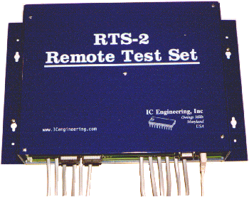
Remote Test Set (RTS-2)
The RTS-2 is designed to allow security protected remote access to cable company VoIP adapters, central office (CO) switches, and premise equipment. The RTS-2 is an 8-port unit that can be linked with up to 7 expansion units, providing access to a total of 49 ports. Each port permits an existing line be split between CO and CPE equipment. The RTS-2 maintains any existing connection between the CO lines and the premise equipment until accessed. Separate RJ-11C jacks provide a pair for the CO side, which is mandatory, and another pair for the normally connected premise equipment, which is optional. An RJ-21X interface is also available. Either loop- or ground-start lines may be utilized.
RTS-2 Features
The first CO line connected to the RTS-2 unit is used to access the device. Upon the specified number of rings, the RTS-2 answers the call and provides an access prompt. The caller has a programmable amount of time (nominally 15 seconds) to enter a correct Test or Program code in DTMF (up to 12 digits). Once accessed with the Test code, the unit is placed into Test Mode, and test calls can be placed through any of the remaining ports.
The outgoing port can be seized, permitting the user to detect dialtone and DTMF dial through; or, the user can pass a number to the RTS-2 to be dialed, and have it automatically seize the line, detect dialtone, and dial the desired number locally, using either DTMF or rotary pulse signaling. During the test call, the RTS-2 can be commanded to generate a hook-flash for CO feature access. The accessor can disconnect from the test call on the outgoing port, and remain in Test Mode, ready to place a new call on the same or a different outgoing port.
A port can be tested for the presence of ringing voltage. CO lines can be monitored while left on-hook. Tone levels can be measured from the access (incoming) and the outgoing ports. The port number may be remotely queried.
The RTS-2 generates test tones (400, 1000, 3000 Hz @ 0 dBm level) which are activated upon command. Individual ports can be configured for responder behavior, so that the device automatically answers and provides a 1000 Hz tone without access codes.
Individual ports can be configured for call forwarding, using either Telco features, or via through dialing to port #1. A line identification function is also available. All port functions can be configured simultaneously (only one can be used at one time).
The RTS-2 maintains a peg count of: Test Mode accesses, signifying the number of times the device has successfully received the Test code; Program Mode accesses, signifying the number of times the device has successfully received the Program code; access Failures, signifying the number of times the device has answered the line and timed out prior to receiving a correct Test or Program code; access Answers, signifying the number of times the device has answered an incoming call; and active Minutes, signifying the number of minutes the device has had active use. Each of these counts are six digits, and roll over from 999999 to 000000. These five counts can be remotely queried.
A logging port is available for connection to a printer, computer, or modem for security purposes. This reports all activity through a built-in RS-232 port.
If the caller uses the Program code to access the RTS-2, the unit is placed into Program Mode, and permission is granted to change the device operating parameters.
These audio recordings demonstrate how the RTS-2 is accessed manually, access line identification is performed, test calls are placed, and the RTS-2 is released.
The above example utilized dialing from the access point through the network to the end office. Other RTS-2 commands are available for redial. Additional sound clips demonstrating automatic RTS-2 access are available on the ARONTS Information page.
ARONTS Application
The RTS-2 ports can be located in the CO, and connected to lines with various classes of service. Insofar as test boards with these lines may already exist, connected to test telephones, the RTS-2 can use these existing lines. The RTS-2 directly connects the telephones (CPE equipment) through to the CO lines when the RTS-2 is not accessed. This permits the test lines to be used locally with the telephones, and remotely with the RTS-2, without doubling the number of test lines required. An RJ-21X interface can be used which permits connecting to the device using a 66 block with cross connect wiring. The unit may be powered directly from a 24-52 volt DC supply.
The RTS-2 may be accessed remotely either manually or with the ARONTS equipment. Test calls can then be placed on the connected CO lines of various classes of service. The dialing plan can be tested with local, long distance, and feature calls. The hook-flash option permits some features to be tested, such as conference calling and call waiting.
Command Summary
After the RTS-2 is placed into Test or Program Mode, DTMF digits are used to issue commands. Distinctive tone sequences acknowledge command acceptance or rejection due to an error. Commands 0 through 8 are available in Test Mode; all commands (0 through 9) are available in Program Mode. However, it is recommended that Test Mode be used unless the device's operating parameters are planned to be changed; this provides protection from accidental device modification.
Commands available from Test or Program Modes:
00: Hangup
01: Exit Test
or Program Mode; provide Access Prompt
02tt:
Modify timeout for commands 1-4, 71-74,
81, this session; tt=00-99
seconds
040: Standard
call in-progress commands (###, ##0,
##8), this session
041: Alternate
call in-progress commands (*##, *#0,
*#8), this session
05dnn...n#[#]:
Callback to telephone number nn...n,
dial type d=2-4
1l:
Seize line l
2lnn...n#[#]:
DTMF dial telephone number nn...n
at standard rate on line l
3lnn...n#[#]:
DTMF dial telephone number nn...n
at slow rate on line l
4lnn...n#[#]:
Pulse dial telephone number nn...n
on line l
5l:
Listen for ringing on line l;
exit with #,
answer with *
(v1.3 and later)
60: Identify
the unit number, 6 digits
61: Identify
the incoming line, 1 digit
62: Read the
number of Test Mode accesses, 3 [6] digits
63: Read the
number of Program Mode accesses, 3 [6] digits
64: Read the
number of access Failures, 3 [6] digits
65: Read the
number of access Answers, 3 [6] digits
66: Read the
number of active Minutes, 3 [6] digits
67: Read the
firmware version, 2 digits
68: Read the
ROM checksum, 2 digits
71: 1000
Hz test signal at 0 dBm level
72: Test signal
of programmable frequency and level
73: 3000 Hz
test signal at 0 dBm level
74: 400 Hz test
signal at 0 dBm level
While commands 71-74 are in progress exit with #
v1.4 and later: exit with *
if alternate call in-progress commands selected (041)
81l:
Monitor line l,
l=2-8
82: Measure
and store signal level on access line
83: Read previously
stored signal level, 2 digits
84: Playback
DTMF digits; exit with #
While commands 1-4, 81
are in progress:
### [*##]:
Release line and return to Test or Program Prompt
##8 [*#8]:
Measure and store signal level on outgoing line
While commands 1-4 are in
progress:
##0 [*#0]:
send a hookflash
##1 [*#1]:
Transmit 10 second 1000 Hz test signal at 0 dBm level to outgoing line
(v1.4 and later)
l = 1-8
line number
n,c
= 0-9,
A-D
digit
*: Cancel current
entry
The 9 commands must be issued from Program Mode:
90173: Initialize
all parameters
90249: Clear all counts (62-66
commands)
91cc...c#cc...c#:
Set the Test Code to cc...c
(identical entry)
92cc...c#cc...c#:
Set the Program Code to cc...c
(identical entry)
93ppvvv:
Write value vvv=000-255
decimal into parameter pp=00-98
94pp:
Read parameter pp=00-98,
2 hexadecimal digits